Share This Article
Photon-Counting CT Room Planning: Power, Cooling, Structure and Workflow
Photon-Counting CT Room Planning: Power, Cooling, Structure and Workflow
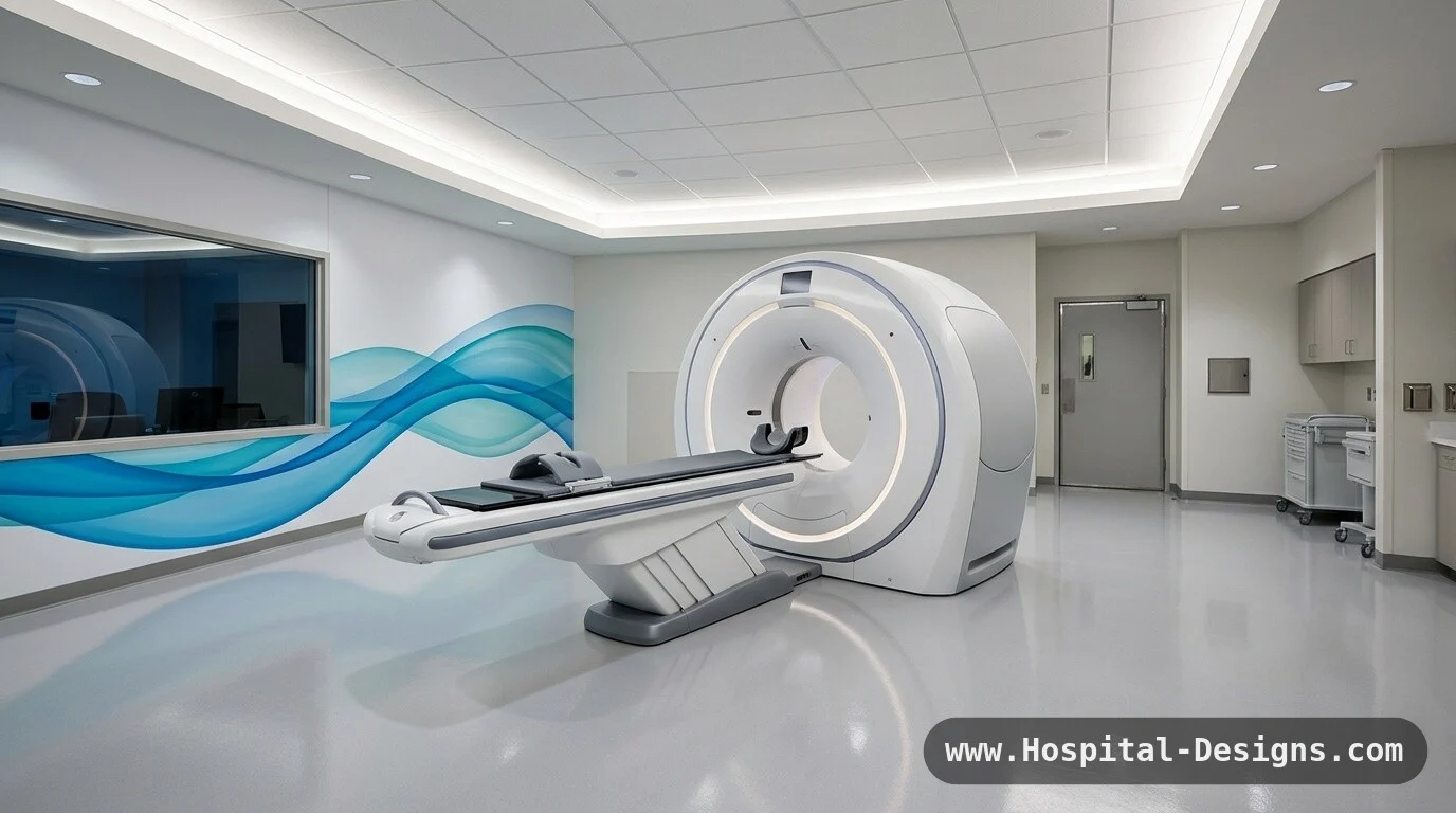
A new scanner technology does not change the basics of a CT suite, but it does change the questions the design team must ask early: how heavy is the gantry, how much cooling and power does it need, how much data will it generate, and will the room still work when the next upgrade arrives? This guide turns the PCCT announcements into a planning checklist for hospital designers and estates teams.
Planning principle: plan the room for the manufacturer’s data, not for the brochure. Use brochure claims to understand the clinical case, and the site planning guide to draw the room.
1. What Is Different About Photon-Counting CT
- Detector: direct-conversion detectors resolve photon energy, enabling spectral imaging from a single scan, and fine spatial detail.
- Clinical focus: vendors position the technology for cardiac, thoracic, neurological, oncological and musculoskeletal work.
- Data: spectral, high-resolution datasets are larger than conventional CT and put more load on networks, storage and reconstruction hardware.
- Dose and workflow: claims on dose and throughput are vendor-specific; treat them as inputs to the clinical case, not as design assumptions.
2. UK and US Planning Frameworks
| Topic | UK | US | Design implication |
|---|---|---|---|
| Room planning | HBN 06 for diagnostic imaging, with the manufacturer’s site guide. | FGI Guidelines and the manufacturer’s site guide. | Start from the site guide; use the guidelines to check clinical adjacencies and clearances. |
| Shielding | IRR 2017, RPA-designed shielding, often following published guidance. | NCRP Report 147 and state requirements, by a qualified expert. | Re-run the shielding assessment for the actual scanner, workload and technique mix. |
| Product status | CE/UKCA marking and MHRA registration. | FDA clearance or approval, which may be pending for new models. | Do not commit to a layout for a model that cannot yet be sold in your market. |
3. Structure and Delivery
- Confirm gantry and table weight, and floor loading with the structural engineer, including point loads during installation.
- Check the delivery route: lift capacity, corridor widths, door heights, turning space and a temporary opening if needed.
- Provide a flat, level floor and vibration criteria in line with the manufacturer.
- Plan for future replacement: a room that cannot be re-equipped without major works becomes a constraint.
4. Power, Cooling and Environment
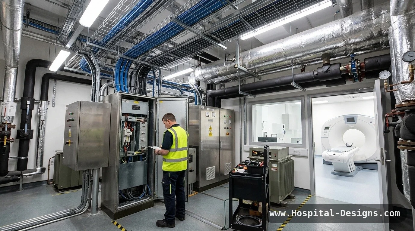
- Power: dedicated, stable supply sized to the manufacturer’s requirement, with surge protection and an agreed UPS strategy for the console and reconstruction systems. See our essential power design guide.
- Cooling: scan room and equipment room heat loads, and where the system uses water cooling, a resilient chilled-water source with monitoring.
- Temperature and humidity: keep within the manufacturer’s range at all times, including during a plant failure.
- Acoustics: plan for equipment noise in the equipment room and plant. See our hospital acoustic design guide.
5. Shielding and Safety
CT shielding is driven by workload, scatter and occupancy, and a new scanner can change the workload through faster scanning and higher patient numbers. Ask the RPA or qualified expert to reassess, and keep the assumptions with the building records. For the wider shielding mindset, see our guide to linac bunker design.
6. Data, Network and IT
- Agree network bandwidth to PACS and storage with IT before ordering, since spectral datasets are larger.
- Allow space and cooling for reconstruction servers, and cybersecurity arrangements for connected equipment.
- Plan remote service access in line with the hospital’s security policy.
7. Workflow and Patient Experience
- Control room with clear sightlines to the patient and door, and direct access to the scan room.
- Changing cubicles, a contrast preparation area and a recovery or waiting area close by, with trolley access for emergency cases.
- Adjacency to emergency, ICU and cardiology, depending on the clinical case.
8. Common Mistakes
- Planning from a launch brochure rather than the site planning guide.
- Ordering a model that is not yet cleared for sale in the market.
- Reusing the old shielding assessment without review.
- Underestimating data load on the network and storage.
- Cooling and power sized for the old scanner.
- No delivery route or future replacement strategy.
9. Review Checklist
- Is the model available and cleared in your market, and is the site planning guide issued?
- Has structure, delivery route and vibration been checked?
- Are power, UPS and cooling confirmed in writing by the manufacturer?
- Has shielding been reassessed by the RPA or qualified expert?
- Are network, storage and cybersecurity agreed with IT?
- Does the workflow suit emergency and outpatient use?
Conclusion
Photon-counting CT is a clinical step forward, but a room is still planned by weight, power, cooling, shielding, data and workflow. Treat each new model as a package of requirements, confirm it with the manufacturer, and design the room so that the next upgrade does not mean demolition.
Key References and Further Reading
- Radiology Business — Key trends in medical imaging systems at RSNA 2025.
- AuntMinnie — GE HealthCare features new MRI scanners, PCCT system.
- NHS England — Health Building Notes (including HBN 06).
- NCRP — National Council on Radiation Protection and Measurements.
Editorial note: This article is an independent design overview. Product information comes from public manufacturer and trade-press announcements and may change. It does not replace the manufacturer’s site planning guide, current standards, or advice from a qualified radiation protection expert and engineers.
We would like to hear your ideas on the design process and any stories you would like to share about how your workplace is influenced by the same via the Contact form.
About the Author:
Harry McQue is a hospital Design & Equipment Manager with Post Graduate degrees in business management and information technology. Harry has 20+ years of international experience ranging from working on hospital projects in Dubai (Middle East) to over £1 billion hospital projects in the UK & Europe. You can benefit from his experience at: hospital-designs.com. If you have current or upcoming projects, big or small or topics that you would like his advice on, you can get in touch via the Contact form.
Use permitted only with prior authorisation. Please contact for permission or guidance.